A recent request from one of my followers Mr. Raja Gilse (via email), prompted me to design a DC double cellphone charger circuit that is able to facilitate charging of many cell phones simultaneously, let's learn how to make the circuit.
How DC to DC Charger Works
I have already explained regarding a couple of DC to DC cellphone charging circuits, however all these are designed for charging a single cell phone. For charging more than one cell phone from an external DC source like an automobile battery, requires an elaborate circuit.
The Circuit Request
Dear sir. Please tell me that what alterations should i do, to charge two mobiles at a time from your "12V BATTERY OPERATED CELL PHONE CHARGER CIRCUIT".(from bright hub) I am using the circuit from last 8 months, it's fine. Please post that article in your new blog also.
Dear sir, i tried so many time to post this comment in your blog in the "simple dc to dc cell phone charger circuit" but in vain. Please answer here~ Sir, i used another 10 ohm 2 watt resistor in parallel with the existing one, as i don’t have the higher watt resistor. It’s working fine. Thank you very much, i have one doubt, earlier, in bright hub in the same article you told to use 10 ohm resistor, but here it is 5 ohm which is suitable ?
I have another question out of this article; please guide me could I use three 1N4007 silicon diode instead of one 1N5408 silicon diode? My aim is to allow 3A current in only one direction. But i don’t have diode of 3A i.e. 1N5408. As 1N4007 is of 1 amps capacity could use three 1N4007 in parallel and like wise for 5A five 1N4007 in parallel, because i have number of 1N4007
rajagilse
Solving the Circuit Request
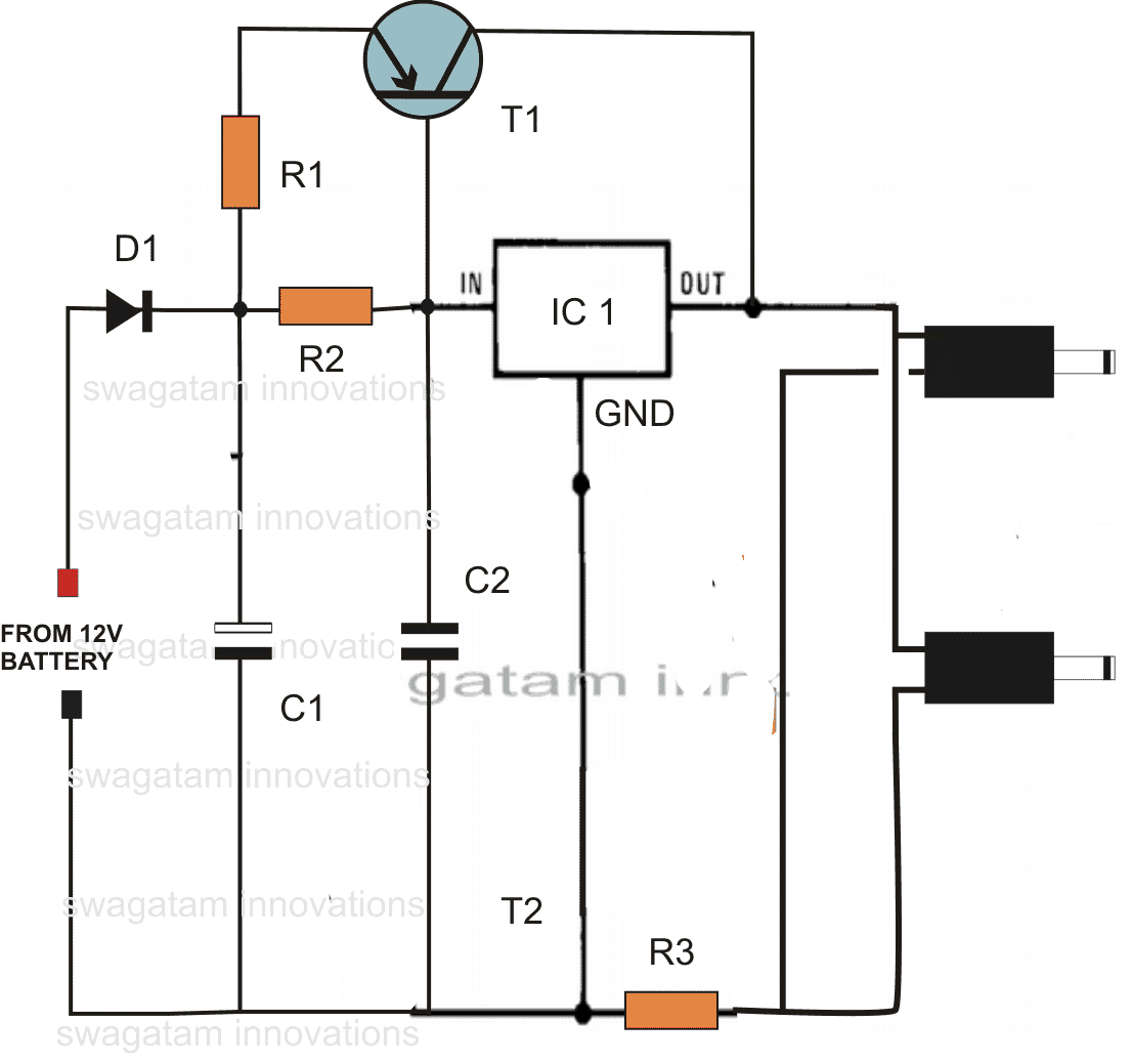
Hi Rajagilse,Use the following DC double cellphone charger circuit given below:
Hi Raja,
As you increase the limiting resistor value, the charging becomes slower, therefore a 5 Ohm resistor would charge the cell phone faster than a 10 Ohm, and so on. I'll check the problem with the commenting in my blog...however other comments are coming normally as usual! Let's see. Thanks and Regards.
Parts List
R1 = 0.1 Ohms 2 watt,
R2 = 2 Ohms 2 Watt
R3 = 3 Ohms 1 watt
C1 = 100uF/25V
C2 = 0.1 discT1 = BD140 D1 = 1N5408
IC1 = 7805
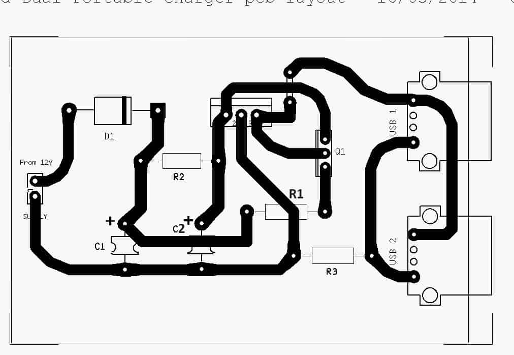
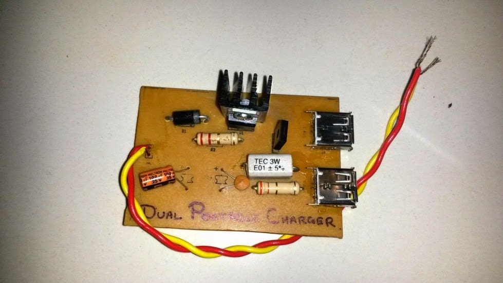
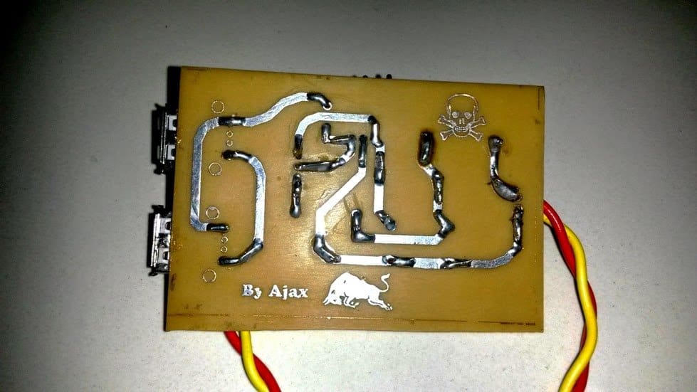
PCB Design
The circuit of the double DC cell phone charger was successfully tried and built by Mr. Ajay Dussa over a home designed PCB, the following images of the PCB layout and the prototype were sent by Mr. Ajay.
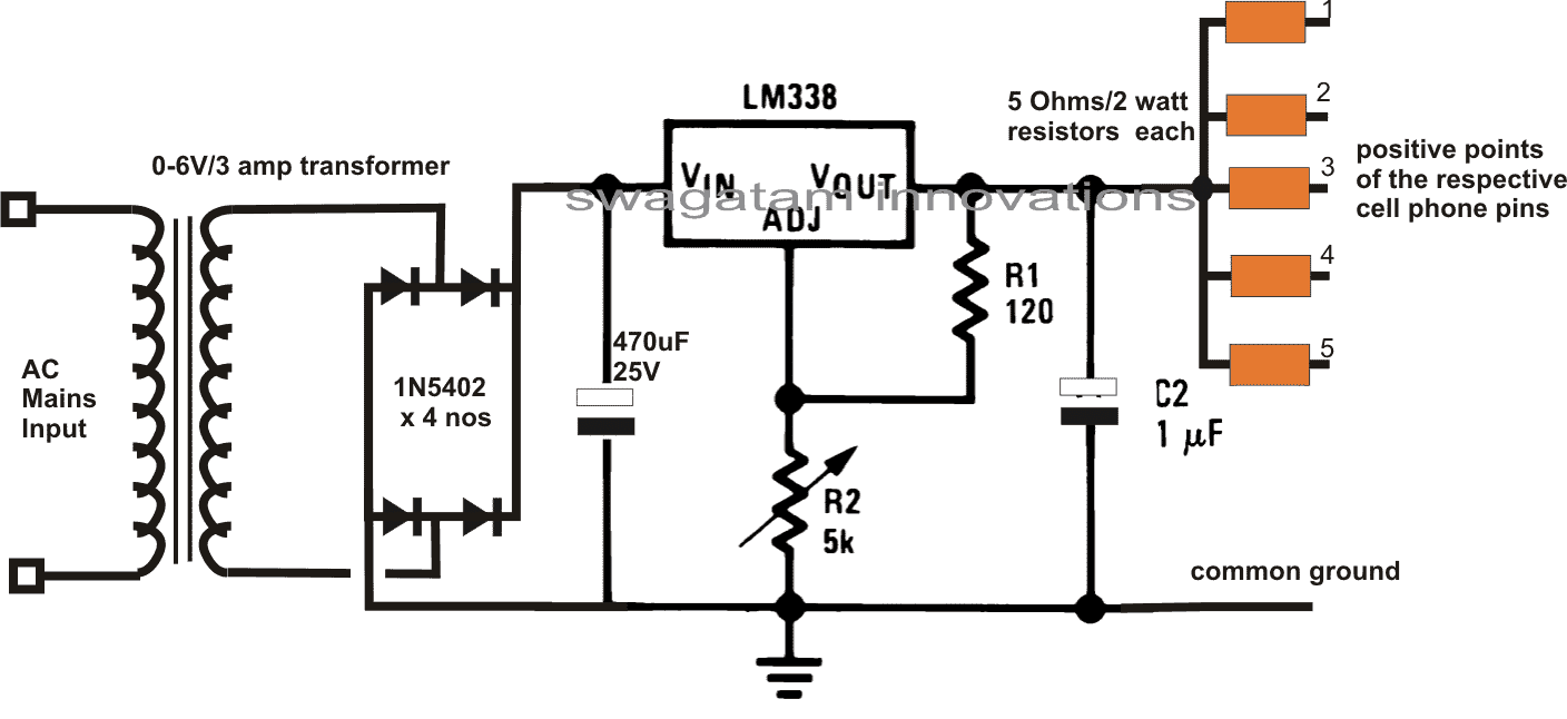
4 to 5 Cell Phone Charger Circuit
The following circuit can be used for charging as many as 5 cell
phones at a time. The circuit employs the versatile IC LM338 for
producing the required power. The input is selected to be a 6V but can
be as high as 24V. A single cell phone can also be charged from this
circuit.
The circuit was requested by Mr. Ram.
- TESTED ARDUINO PROJECT KITs AVAILABLE
Now you can purchase readymade and tested Arduino projects and Kits from here, at very affordable prices, for around Rs.3500/- or $54 each.
For more details just drop me an email at: homemadecircuits @ gmail.com
Please Join the Forum below for Comprehensive Discussions
-
- Topic
- Voices
- Freshness
Get New Circuits in your Email
About Me

Swagatam is an ardent electronic researcher, inventor, schematic/PCB designer, manufacturer, and an avid publisher. He is the founder of https://www.homemade-circuits.com/where visitors get the opportunity to read many of his innovative electronic circuit ideas, and also solve crucial circuit related problems through comment discussion.
Mark says
Hi hello mr swagatam. Good day.. let me ask.. why is it my lm7805 getting heat if I am going to charge my cellphone.. these are my components I used, lm7805, cap.104, cap. 10uf/16v, batt.12v, 2amps.
Thanks in advance
Swag says
Hi Mark, 7805 will become hot if current through it is above 200mA, it is a standard drawback of all linear ICs, you must attach a large heatsink with the IC to control the heating.
Aminu Yahaya Ibrahim says
In my next circuit design, I'll like to use 7805 and TIP 36 and high current power supply to charge many phones like 50 depend on the input power supply current. Is this feasible Sir?
Swagatam says
yes that's feasible by proper calculation…please refer to this article for more info
http://makingcircuits.com/blog/2017/06/7812-7805-ic-current-booster-circuit.html
Aminu Yahaya Ibrahim says
I did it…
But, Am afraid if the phones may damage due to the higher current from tranfor that pass directly to the higher current transistor TIP36.
I used 50A tranfor and TIP36 with the circuit you have suggested to me and I added this 5ohm 2watts resistor to each USB port.
Base on this connections, Sir Is it safe to charge even only one phone with my 30 USB ports cell phones charger?
Swagatam says
Before connecting you can check the output voltage from the set up, if it shows a constant 5V then it's safe, alternatively instead using the TIP36 network, you can use 2 or 3 7805 ICs in parallel…that would allow you to get rid of the mess and apprehensions with regards to the outpass BJT and it's working reliability…
http://www.homemade-circuits.com/2013/09/connecting-voltage-regulators-78xx-in.html
Aminu Yahaya Ibrahim says
If the current may not affect the phone, then my fear has gone… I had used the way 7805's are linked together in the link you shared and connect 5 nos of 3055 to the single LM317. The output of each 3055 is not connected and each should charge only 4 phones at sametime.
I hope my idea is okey, Sir.
Swagatam says
current will affect if the voltage is increased beyond the phone tolerance or specifications, as long as the voltage is within the specified limit, current will have no impact.
you must connect 4 small value resistors with each 2N3055 output so that the phones are charged uniformly
Aminu Yahaya Ibrahim says
thanks Sir.
And, for the resistors, you suggested I can use any ohms bellow 5ohms. I have doubt as follows.
1. Is the watts critical, or can I use lower watts like half (1/2)watts?
2. Is the resistor's value has effect on charging speed?
Thanks very much Sir.
Swagatam says
You can start with 5 ohm 2 watt and check the charging time…if it's too slow you can reduce the value appropriately until the speed is optimal.
lower watt will heat up the resistors..therefore appropriate wattage must be used.
yes resistor value will affect speed.
Aminu Yahaya Ibrahim says
Sir I built this circuit using LM317 and 3055 to get 5V/3A and I supply power to the circuit using Laptop Charger rated at 19v 3.5A.
the problems am facing are over heating, voltage droup to 4.7 at each pots if a cell phones are connected.
Sir, what may course these problems?
thanks
Swagatam says
Aminu, the voltage has to drop, and it must drop below 4V..4.7V looks too high…make sure to connect a limiting resistor at the output of the charger…you will have to calculate it using Ohms law depending on the cellphone's battery power
Swagatam says
connect the 3055 with LM317 heatsink using mica isolator this will protect the 3055 also from overheating through the IC317's internally thermal regulator…
Mukesh says
0.1ohms not available shop gave me 100kohms what to do? Give alternate to 0.1ohms
Mukesh says
In my mobile charger it says turbo 1 9v 1.6A and turbo 2 12v 1.2A standard 5v 1.6A what these means?how it knows which mobile charging or mobile will pull such current? Replacing 7805 to 7809 or 7812 will work?how to limit to 1.6A?
Swagatam says
yes you can try that, first try with 7809 if it shows improvement then you can try with 7812
the mobile charger is equipped with a boost charger which converts 5V to 9V or 12V from a USB port…..78XX will automatically limit the amp to 1 amp…..use a large heatsink with the IC.
Mukesh says
How to modify so that it will support turbo charge please
Mukesh says
Hi bro i have been trying lot of circuits since i love electronics it was my hobby i woulf like to try this circuit i would like to know is it possible to convert the circuit to turbo or quick charge?how to alter thank you.
Swagatam says
Hi Mukesh, you can try the following concept:
http://www.homemade-circuits.com/2012/01/how-to-build-simple-pwm-controlled-dc.html
This will help you to get a turbo charging but the pot will need to be perfectly optimized for getting the results, otherwise the phone will keep rejecting the charging.
Kesava Raj says
Very very thanks sir
Kesava Raj says
Thank u sir….
Another 1 doubt…
7805 o/p needed diode sir….
Bd140 o/p and 7805 o/p..both o/ps r connected same…it will damage the 7805 ic sir…or we need to place diode …IN5408…
Swagatam says
diode is not required, because the transistor collector voltage can never surpass the 7805 output voltage, in doing so the 7805 will get reverse biased and stop conducting which in turn will also stop the transistor from conducting..this creates a deadlock ensuring a constant 5V at the output
Kesava Raj says
Hai sir….
I have some doubts in 1st circuit….
With out using BD140 transistor it will work…
What is the purpose of using transistor…
How the transistor will give 5v o/p 1A….
Swagatam says
Hi kesave, without the transistor the iC alone will not be able to deliver more than 1.2 amps, which might not be sufficient for charging two smart phones together…the transistor boosts the current to more than 2amps…
Jitendra says
which one cell phone mobile charger circuit is good and safe use charging from bike 12v battery ?
Anonymous says
which mobile charger circuit is best for use bike bike from 12 volte ?
your advice to me
Swagatam says
mobile charger cannot be used for charging 12V batt
Anonymous says
my means was which mobile charging circuit is good for using in bike for mobile charging
Aminu Yahaya Ibrahim says
Good Day Sir,
Sir, I did not find this 5 ohms resistors. In the market, I can found only 10, 18, 1.5 ohm and rest.
Sir is there any alternative?
Thanks!
Swagatam says
Aminu, the 5 ohm is not critical, initially you can try using 1.5 ohm, if it does not charge try two in series and so on…
ADNAN AHMAD says
Hello Swagatam,
Let me appreciate you for a wonderful and useful helping work for people like me who know a little. I would thankful to you if you share diagram in large size as I am unable to enlarge it. 2ndly please share picture of built circuit by you. It will clear more https://www.homemade-circuits.com/2012/05/dc-to-dc-double-cell-phone-charger.html?m=1things
Regards
Adnan
Swagatam says
Thank you Adnan,
The first circuit is already big enough to see everything clearly.
It was a long time ago, so finding the circuit and uploading the images now will be difficult.
sim dep says
This is good website.Thank you for this post a comment
John Vincent Rioveros says
hello sir. we reduce the values of resistor in both circuit like what you said but we still end up whit the same output as before. we can't still charge a samsung phone but we can charge a pocket wifi. what else do you think our mistake? thank you sir!
Swagatam says
hello john, some cell phones are too critical with the charging voltage and refuse to accept even minor differences.
in the second diagram, try to tweak and fine tune R2 until the cell phone just accepts the charging voltage….this may take some time and effort.
John Vincent Rioveros says
sir, we also tried the last circuit given but we still have the same results. we will be trying your suggestion regarding r3. we will update you to what result re get regarding the r3. thank you sir!
Swagatam says
reducing the resistor values in both the circuits should help initiate the process…
John Vincent Rioveros says
HI Sir,
I was working with the circuit given above with the materials the same as what you've listed sir. I was able to charge a pocket wifi with a battery specs of 3.7V, 4.3Wh; however, failed to charge a samsung phone with a battery specs of 3.7V, 4.4 Mh, also, the IC and the resistor is heating up. What might be the problem with this sir? i used a motorcycle batter 12V, 4Amps.
Thank you in advance sir.
Swagatam says
Hi John, try reducing the value of R3 to some lower value and check the response, or you can also try the last circuit for more reliable results.
Daniele says
Hi sir,
I would know on the circuit of 5 phones charger the meaning of the common ground, especially the scope of one of the four diodes (the one on the bottom-left) it has the anode at the common ground and the cathode at the ground of battery/transformer, so should I use two different ground or I have to connect that component at the same ground?
Thanks in advance for the answer.
Greetings!
Swagatam says
Hi Daniele, all the cell phone negative wires needs to be connected with the line indicated as the "common ground"
I could not understand what you are trying to say regarding the bridge diodes, please click the diagram to enlarge….the line break indicates "no connection" across the overlapping lines near the diode bridge.
Mayra Brillas says
Sir, what is the maximum time to full charge phone batteries using DC to DC Double Cell Phone Charger Circuit. Thank you very much!
Swagatam says
Mayra, it could be between 2 to 4 hours
Daniele says
Hi sir,
thanks for the answer, you're very kind.
I have just another question about the functionality of the charger project of 5 phones. Why it's necessary put a transformer at the start of circuit? The LM338 and the diodes aren't enough to manage the 12V battery? Thanks in advance for any advices.
Have a nice day!
Swagatam says
Hi Daniele, the transformer supply is shown instead of a battery, for getting a mains operated charging set up.
If a battery operation is intended then the transformer and the bridge network will need to be removed and the battery connected as shown in the first diagram.
Daniele says
Hi Sir,
I would make the 4-5 phones charger and as input I would put a battery that is the output of another your project (http://homemadecircuitsandschematics.blogspot.de/2012/04/how-to-make-solar-battery-charger.html). Do you think I could use 12v/3A with a solar panel of 150W/12V on the other circuit? Should i put a protection (as a switch) from the one circuit to the other?
Swagatam says
Hi Daniele, the solar panel peak voltage rating should be at least 3 V higher than the battery voltage for initiating the charging process optimally, so a 15V panel is recommended, the wattage is immaterial and can be anything.
Ajay Dusa says
It worked!!!!….I connected the LM338 according to the datasheet which shows pin1-Adj,pin2-Vout,pin3-Vin. Also it was the output of Transformer(6V/3amp).Thank you for your Help…
Swagatam says
OK great! thanks for informing.
Ajay Dusa says
I have used 6v/3amp as the input to LM338.Should be the input voltage more than 6v to charge all my phones?
Swagatam says
yes that could be one of the reasons, By the way with a 6V supply you wouldn't require the LM338 stage, simply connect the output from the 6V source via the resistor network to the cell phones…..try this most probably all cell phones will start charging
Swagatam says
in the diagram above a 6V transformer is shown whose output would become around 10V after rectification….so the input could be assumed to be 10V here
Ajay Dusa says
Sir,I had made the 4-5 Charger Circuit But the problem is when I connect two or more loads at the output out of which only one is working the others remain as it is.Only 1 phone is getting charged out of the 4 connected phones.I wanted to charge all 4-phones simultaneously But it's not working when I tested out on Breadboard.
Any Suggestions ?
Swagatam says
Ajay, what is input current that you have used? It should be able to supply minimum 3 to 5amps
Ajay Dusa says
I am trying to make the 4-5 Cell phone charger.Could I use 6v/1Amp transformer….in place of 3Amp..is it sufficient….because 3amp transformer is not available at our nearby store……Could you tell the least Amp that can be used……in the circuit…..without affecting the output……
Swagatam says
1 amp will not be sufficient, 3 amp is the recommended optimal limit, otherwise the phones will take much longer to get charged.
Ajay Dusa says
I completed the above 2pin charger and is working fine…the only problem I am facing is with the ic 7805,when I apply 12v or more the ic heats up quickly although i had attached a heatsink on it…As soon as the ic becomes hot It shows that the phone is charging but the percentage of the charging level remains the same after a while…….so what should I do Please suggest me…..Should I attached a bigger heatsink on it………….
Swagatam says
check without connecting the cell phone, if it still heats would mean something wrong in the connections or the IC, otherwise it's normal, just increase the heatsink dimensions
……however, that shouldn't happen under any circumstances if the circuit is built exactly as given. I suspect a fault in your circuit…
Anonymous says
Hi Sir,
I need a cellphone charger circuit powered from a 12v solar cell to charge one or more cellphones. Which one can I use?
Thanks,
Tshepo
Swagatam says
Hi Tshepo,
you may try the above circuit, it will do the job.
Anonymous says
sir, what would be the value of DIODE placed after the solar panel so that the power from batteries wont go back to solar panel when there's no sunlight?
Swagatam says
assuming the solar panel current is not over 5 amps, a 6A4 diode may be used.
Anonymous says
hello sir..i just want to ask, what is the OUTPUT and INPUT VOLTAGE, and OUTPUT and INPUT CURRENT of that circuit above..the 4 to 5 Cell Phone Charger Circuit?
Swagatam says
output voltage will need to be set to around 4.5V by adjusting the given preset. Input current should be around 3 amps
Anonymous says
good day to you sir..will you pls explain how the circuit works or the functions of these components from your circuit??
1N5402
470micro farad/25V
r2 5k
r1 120
1micro farad
5ohms/2watts
i would greatly appreciate you responds sir..thank you
Anonymous says
hi sir..is it okay with you if we will use your 4-5 cell phone charger circuit to our project?
another thing sir, is it possible if we connect it to a solar cell?what can be the possible consequences if we do it so?thank you for your response sir..
Swagatam says
the solar panel voltage should be under 30 V, then it would be safe to use it with this circuit.
Anonymous says
hello sir..is it okay with you if we will use your 4-5 cell phone charger circuit to our project?
Swagatam says
yes, you can use the circuit for your project.
Anonymous says
sir can you post a mobile charger which is dc to dc multiple charger same as capable for 4 to 5 cellphone
Swagatam says
It's already been given in the above article….
Ram says
Sir, how can we Thank you for all you kindness and effort. One more question can we make charger by using 5 ohm / 2 w resistor from 6 v battery ( want to add charging ph option to emergency light which have 6v 4ah battery and 500ma transformer for charging)
Regards
Ram
Swagatam says
My pleasure!
Use 10 Ohms/2 watt resistor, it should work.
Regards.
Leo Joseph says
1) Sir can we charge a mobile using a mobile battery externally? )) 1
2) Is there any danger in charging a mobile battery externally using the normal charger?
3) How can we connect to the inbuilt thermister and reduce the danger?
Swagatam says
Yes you can charge a cell phone using another bigger cell phone battery which should be fully charged at 3.8V via the cell phones charging socket.
Yes it is dangerous to charge a cell phone battery externally…
It's not recommended modifying a cell phone circuitry….
Talakshi says
i HAVE A VOX MOBILE BATTERY WHICH IS NOT GETTING CHARGED AT ALL EVEN AFTER KEEPING IT FOR CHARGING FOR MORE THAN 2HRS WHAT DO I DO
Swagatam says
What is the AH of the battery? If it's more than the NOKIA 5LC then it will take more time….
ravi takkar says
sir i too want to meet u for designing for mobile phne charger circuit plz respond asap ma email id is takkar012@gmail.com and ma mobile no is 9729777730
Swagatam says
Actually I'm already too busy with many assignments so it would be difficult meeting physically….you can feel free to ask any question here, if feasible I'll surely help you out.
Regards.
ravi takkar says
dear sir,
thks to responding me,sir actually i want to start ma own unit of manufacturing n want to go deep in the same or in mobile phone charger circuit so plz guide me from where to i would start as a ma mentor and give me some knowlege of capicitor diode n about the designing of circuit.
thnks
Swagatam says
There's a tough competition in the market, things like cell phone chargers have become too common….so I'll suggest you first do some market study….costing, set-up etc.
Take a cheap cell phone sample, open it and find the approximate bulk costing of all the material….if you are convinced that you would be able to provide the item cheaper than the market rates then you could probably proceed.
ravi takkar says
dear sir
i ravi takkar so much keen to know about all this funds acturally m a regional head in mobile phone accessories industry n nw making planning to go deep under it but unble how and from where to start specially mobile phone charger manufacturing becoz accept this all other part of the same thing importable from china but i think i can make myself leader in this segment .hoping for the favourable resoponse form ur side .
thnks n regards
ravi
Anonymous says
please refer to the link
http://www.kpsec.freeuk.com/projects/dice.htm
the ic 555 is not giving me pulses what is the problem instead of 0.01uF i used 10uF it should give output even if the frequency changes but it is not working does the electrolytic capacitors voltage rating causing a problem please reply me fast
Swagatam says
The circuit looks very straightforward and should work immediately, especially the 555 stage, it's very standard, use an LED/resistor from pin#3 of 555 to ground and try different caps at pin#2, check to see the LED flashes or not..
Cap voltage should be twice the value of the supply voltage, is not that critical…
Anonymous says
thank you sir for the link i really got lots of information from this plzzzz put on a circuit to make use of phone batteries as torch and also that the torch consists of the charger ciruit for these batteries
Swagatam says
Thanks!
I'll be soon posting a circuit of an emergency light using a cell phone battery….I'll let you know when it's published
Anonymous says
the resistor i got from the shop 0.1 ohm 2 watt has some color codes on it.
brown black gray gold
Swagatam says
Please refer this link:
http://www.hobby-hour.com/electronics/r1-r82-resistors.php
Anonymous says
wat is the color code for 0.1ohms 2 watt resistor
Swagatam says
It will be a wire wound type, so no color code….
Anonymous says
mean sir we normally connect batteries in series but can connect AA in parallel beacuse parallel combination will cause short circut is it right
Swagatam says
Parallel charging will not cause short circuit but is not recommended due to inefficiencies with the procedures…
Anonymous says
yes sir u r right i wanted to know whether batteries can be connected in series
Swagatam says
Which batteries?….this charger circuit is for cell phones….
Anonymous says
can batteries be connected in parallel
Swagatam says
This circuit is for charging batteries inside cell phone..not to be used directly for Li-Ion batts.
Anonymous says
wat do u mean by 4.5 mah
i want to make led lights or torch operated on cellphone baaterie please suggest me how i connect leds to the battery as emergency light.
means how many leds in serier and how many parallel combination are possible. and please tell me what does the current rating on cellphone batteries mean i.e 900mah, 1000mah,1500mah
Swagatam says
I'll post a new article discussing your topic soon….stay tuned.
John Vrex Andrade says
GOOD DAY Sir:
if a source is 1.5 or 2 volts only is it possible to charge cell phone?
Swagatam says
That's a good topic for discussing, definitely it is feasible using boost converter circuit….. let me try it, if it works i'll surely update the info here soon….thanks.
Anonymous says
but wat abt the wattage will it not affect now.
is this value available beacause i did'nt ask to other shops so i think i would ask someone.
thanks for the circuit and il try your above idea and see
Swagatam says
10nos. 1/4 watts in parallel makes 2.5 watts…..
Anonymous says
sir 0.1 isint available so please suggest me iwent to buy the components but they were not having it.
Swagatam says
Take 10nos 10 Ohm/1/4 watt resistors and put them in parallel to make 0.1 Ohm
Anonymous says
in the above circuit i didn't get resistor of 0.1 ohms instead i got 1 ohms will the circuit work. and y are the wattage rating of these resistors high cant we use a 1/4 watt resistors for this.
Swagatam says
1 Ohms is 10 times more than 0.1, so it won't work.
Resistors which are intended for handling large currents are specified accordingly with higher wattages, so 1/4 watt will burn in those places..
Anonymous says
can these transistors work for my motors pllllllllllzzzz provide me with the circuit please
Anonymous says
http://www.robotroom.com/BipolarHBridge.html
Swagatam says
Use TIP127 for the PNP and TIP122 for the NPN transistors, your motor will start working smoothly, without creating any heat………the transistors you are using at present are underrated.
Anonymous says
can you show me a circuit of h bridge to control my 3v dc motor i made a ciruit using two npn q2n2222 and two pnp2907a transistors but i am not getting any outuput instead the transistors become hot when i connected the motor is it beacause of the package i used t0-18 metal package. plzzzz give me a circuit that will definitely wor for 3 to 12volt motors plzzzzzzzzz sir. plzzzzzzzzzzzzz reply me fast
Anonymous says
are the resistor values available in stores. i am a student and want to make a project. batery charger is my topic so please guide me and instead of the 12 v batter can i use a 6v 4.5mah battery instead
Swagatam says
All the component values are standard and should be easy getting them.
6V/4.5 AH battery will do.
Kiran says
hi sir how can i make bluetooth headset?not an exact one but it should transmitt music and receive in a speaker(wireless)do u know any such circuits?please reply asap.
Kiran says
Hi sir,how to convert 4.8v to 9v? do u have any schematic for this?
siree says
hello sir..
2 and 3 ohmn resister are not available sir, instead of that 2.2 and 3.3 resisters are available. so can we connect them?? by d by sir plz tell me the link or plz explian the functioning of ic 7805 , transistor BD140 and diode IN5408 with diagrams sir and also about the pin diagram of that ic sir. plz sir. i am doing dis sir jus started today.
Tombari says
Thanks for your response but i have typed the key words with no result. Pls post a circuit that clearly shows how to sequence the word WELCOME or OPEN made of LEDS. Pls i eagerly await your response. Also how do i add a circuit here as a contribution? Thanks
Tombari says
Thank you sir for your response and the link you sent me. But the link clearly states that there will be 0 on the display. Can u modify it your own way to inhibit the appearance of the 0? I have a 4510 up/down counter circuit for the dice but i believe you can modify the 4033 version to be easier than what i have. Pls also remember my request for a post about forming words from LEDs. Thanks
Tombari says
Thank u sir for all your good work. Pls can you modify and post the digital electronic dice circuit using IC 4033 that you posted on brighthub here? The old one displays 0, 7 and 8 which are not dice outputs. Secondly, i plead that you make some post about how to use LED to form words with example. Thanks
Rajagilse says
Is is safe to use universal mobile battery charger? To charge li ion battery with ac current? The picturegs in this url
http://1.bp.blogspot.com/-OfhtRV9_Q2Q/TeCv0RAVHTI/AAAAAAAACIw/dwzRpqe1BZ4/s640/universal_Charger.11393034.jpg
siree says
hello sir…
sir plz do for charging of laptop also sir…. i think we gav to chnge the fixed voltage from 5v to 12volts
siree says
hello sir…
i hav a doubt. according to the figure shown we can connect to mobile. but generally for a charger will will b having a pin and from dat pi we will connect to mobile. but how is it possible in this case sir?? can u plz show me the figure of connected circuit wit mobile..
Rajagilse says
Sir, thanks for the information.
I asked the nearest electronic shop for LM3622 IC., but it is not available. So could i use LM317T ? In such a way that i adjust the charging voltage as 4.2v and 200mah current. Is it safer than ic 7805 circuit?
I have another doubt regarding my digital multi meter . It shows 5.05V to 5.15v for the out put of ic 7805and for ic7809it shows9.05v to 9.15v and further more , i adjusted lm 317 with 1.2k and 470ohm resistor as R2 and R1 respectively, to get 4.44v(according to table of lm 317), but my DMM shows 4.54v why it is so? The DMM has error as +/-(0.5%rdg+2dgt). I.e. The reading 4.54 may vary from 4.50v to 4.58v. Not at all 4.44 i.e. Weather my ic is faulty or DMM is faulty
siree says
its really very nice.. thank you.. i too will try this circuit..
Rajagilse says
Sir, i am using your earlier circuit i.e. Single cell charging , to charge mobile battery. With small alteration as you said, i.e. I join another 10 ohm 2 watt resistor in parallel with the existing one. And i charged mobile and external lithium ion battery too. Is it (your earlier circuit)safe to charge charge external li ion batteryi.e. Without mobile?
Rajagilse says
Thanks for the circuit sir. Make alteration in the way that should auto cut off after full charge. Because i an using the mobile battery in 2 torch and radio also. That is why i asked for charging more than one battery. He possible please do it sir